Why a structured framework matters
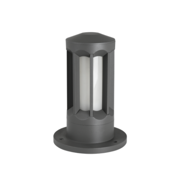
When you retrofit or design outdoor wall-mounted motion-sensor lighting, the invisible problem often isn’t glare or aesthetics — it’s total harmonic distortion (THD) disrupting downstream systems and disrupting reliability. A clear, repeatable framework helps teams predict outcomes and avoid surprises on-site. Start with a systems mindset: fixtures, drivers, sensors, and the supply all interact. If you’re also specifying pathway elements like bollard lights nearby, their cumulative harmonics and inrush currents matter to the same distribution circuit.
Real-world anchor: municipal LED rollouts and what they taught us
Large municipal LED conversions — for example, the well-documented citywide programs in Los Angeles and other major cities — exposed common pitfalls: mixed-driver populations, uncontrolled dimming networks, and sensors added late in the design. Those projects are a useful reference because they’re not laboratory conditions; they’re real grids, real aging transformers, and many fixture models. From consulting on retrofit clusters informed by those rollouts, I’ve seen the same pattern: measure first, then change. That practical stance informs the framework below.
Step 1 — Diagnose: measure THD and its sources
Before swapping fixtures, measure. Use a true-RMS power analyzer to log THD, voltage distortion, and current waveforms during typical events (motion trigger, dusk-to-dawn cycles). Pay attention to baseline THD on the supply, and then capture the incremental impact when a motion sensor engages. Key metrics: THD percentage, peak inrush current, and any flicker frequency during switching. These data guide whether the mitigation must be at the fixture, the driver, or upstream.
Step 2 — Design: choose drivers and components that minimize harmonics
Driver selection is the single biggest lever. Prefer LED drivers with low THD ratings and active power factor correction (PFC) where possible — they reduce harmonic injection into the grid. For motion-sensor applications, choose drivers that tolerate frequent ON/OFF cycles and support soft-start to limit inrush. Consider sensor-embedded drivers or interoperable control modules to avoid introducing additional switching noise through external relay-based sensors.
Step 3 — Integrate sensors and controls thoughtfully
Motion sensors and dimming controls are prime harmonic troublemakers if they’re incompatible with the driver. Use sensors that implement solid-state switching synchronized with the driver’s dimming method (0–10V, DALI, or digital PWM). If you must use relay-switched sensors, add snubbers or inrush limiters to prevent abrupt current spikes. Test sensor-driver pairs in a bench setup before mass deployment — it saves costly field callbacks.
Step 4 — Mitigation hardware and topology fixes
When measurement and design tweaks aren’t enough, add mitigation: line reactors, passive harmonic filters, or active harmonic conditioners at strategic points. For small clusters of wall lights, localized LC filters at the fixture feed can bring THD into acceptable ranges without altering municipal infrastructure. For larger arrays, coordinate with the distribution owner for line-side solutions. Keep in mind: filtering can affect power factor and thermal loading — size components accordingly.
Step 5 — Validate: field testing and acceptance criteria
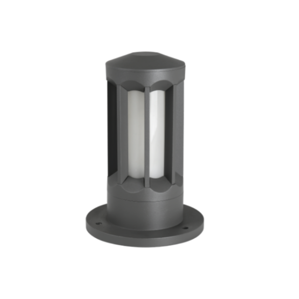
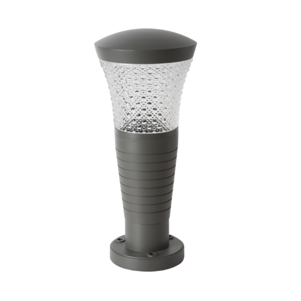
Validation is where projects succeed or fail. Define acceptance thresholds (for example, THD < 8–10% at the branch circuit under peak load) and test under real operating conditions — motion events, nighttime dimming, and full-load daytime. Document results and include them in the punch list. If fixtures like led bollard light are on the same circuit, test combinations; cumulative harmonics can be surprising when mixed models operate concurrently.
Common mistakes and how to avoid them
Teams often skip bench validation, assume compatibility, or buy cheapest drivers without harmonic specs. Another common error: adding sensors after procurement, which leads to mismatches and field failures — don’t do that. Test early, procure for compatibility, and insist on clear driver datasheets that list THD, PFC, and inrush figures. —
Practical trade-offs and alternatives
Sometimes the best mitigation isn’t more hardware but simpler topology: separate critical runs onto their own breakers; stagger switch-on sequences; or replace a problematic subset of fixtures with higher-quality drivers. Passive filters are cost-effective for small installs; active filters work better for larger, variable loads. Each choice balances capital cost, maintenance complexity, and expected lifetime savings.
Three golden rules for evaluating your solution
1) Measure before you spec: baseline data beats guesswork. 2) Specify harmonics-aware components: drivers with PFC and documented THD specs, plus sensors listed as compatible. 3) Validate under load: acceptance testing with motion events and mixed fixture populations reveals real behavior.
Follow these rules and you’ll reduce callbacks, improve power quality, and extend fixture life — the same practical outcomes municipal programs sought when they scaled to thousands of luminaires. Keyida. –