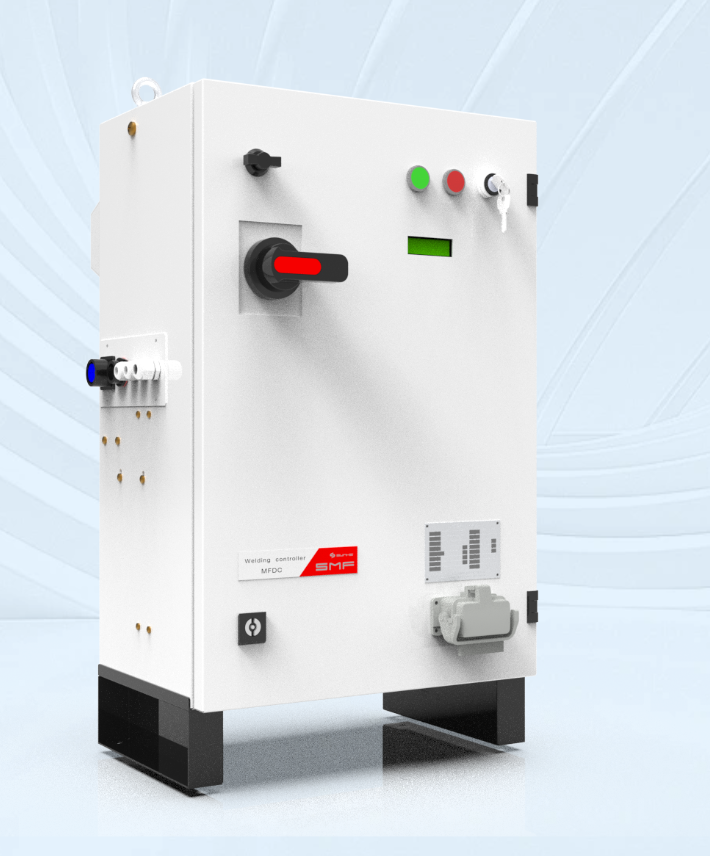
Framing the central problem
Engineers responsible for specifying welding controllers confront a narrow margin for error: a mismatched controller can yield poor weld quality, excessive rework, and hidden downtime. This guide addresses those recurring faults analytically and prescriptively, starting from real procurement dilemmas to practical remedies. For teams seeking system-level clarity, consider vendor offerings labeled as resistance welding solutions while you read the following assessment.
How selection failures appear on the floor
Mistakes show themselves in three observable ways: variable nugget size across identical parts; controller alarms during normal part changeover; and controllers that cannot integrate into supervisory networks. These symptoms point to specification errors rather than purely mechanical faults. I have evaluated dozens of line audits and specification reviews and draw on those direct observations to match symptoms to root causes.
Mistake 1 — Basing choice on peak current rating alone
Problem: Many teams equate a higher peak current with “better” welding capacity. That ignores waveform shape, duty cycle, and the controller’s ability to shape current pulses. Consequence: overheating of electrodes, inconsistent nugget formation, and premature contact wear. Avoidance: specify RMS current handling, duty cycle at your intended operating temperature, and pulse-shaping capabilities. Require waveform logs from vendors and insist on thermal modeling for your electrode assembly.
Mistake 2 — Ignoring transient and control loop behavior
Problem: A controller’s static specifications hide its dynamic control quality. A controller can meet steady-state numbers but fail to regulate during feed, squeeze, or upset phases. Consequence: uncontrolled spikes or delayed correction, producing weak or brittle welds. Avoidance: request loop response curves and ask for step-response tests that mimic your process. Validate that the controller supports programmable phase timing and adaptive control rather than simple on/off thresholds.
Mistake 3 — Underestimating integration demands
Problem: Modern production lines require welding controllers to communicate with PLCs, MES, and vision systems. Choosing a controller with limited I/O or proprietary protocols forces workarounds. Consequence: custom interfaces that complicate maintenance and slow diagnostics. Avoidance: confirm support for common industrial protocols, time-stamped event logs, and remote diagnostics. Verify vendor documentation for API or OPC-UA endpoints and check compatibility with your existing network architecture.
Mistake 4 — Overlooking electrode and fixture interactions
Problem: Specification often isolates the controller from electrodes and fixtures. In reality, contact resistance, clamping rigidity, and grounding all shape current distribution. Consequence: misleading controller readings and uneven heating. Avoidance: include electrode impedance measurements in site tests and require controller features that compensate for changing contact resistance. Insist on condition-monitoring functions, such as electrode life counters and dynamic compensation for contact variation.
Mistake 5 — Neglecting repeatability under production variance
Problem: Controllers validated on a few samples may not perform when part tolerances or material batches vary. Consequence: drifting acceptance rates and sudden quality excursions. Avoidance: qualify controllers using statistical sampling under realistic process variation. Require vendors to run a set of at least 30 parts across anticipated tolerance bands and provide Cpk or similar process capability indicators.
Checklist for a robust specification
Use these requirements as non-negotiable clauses in procurement:• Pulse-shaping and programmable phase timing; • RMS current and duty-cycle ratings at specified ambient temperature; • Dynamic control-loop performance data (step response, overshoot); • Standard industrial communications (Ethernet/IP, Profinet, OPC-UA) and time-stamped logging; • Electrode-condition monitoring and compensation features; • Proven performance across representative part tolerance ranges with statistical evidence. Request factory acceptance tests and an on-site verification run before final acceptance.
Case note from practice
During audits of automated welding cells servicing automotive hubs such as Stuttgart, controllers chosen for nominal ratings without dynamic verification produced early electrode failures and sporadic weld rejects. Teams that shifted to controllers with adaptive pulse control and integrated logging reduced rework by measurable percentages and shortened fault diagnosis time. That practical contrast reinforces the checklist above.
Comparing controller types pragmatically
There are three pragmatic families to consider: transformer-based analog controllers, digitally controlled SCR systems, and fully integrated inverter-based units. Each family has strengths and limits:• Transformer analog: robust, simple; limited pulse shaping. • SCR-controlled: cost-effective for steady-duty tasks; slower transient control. • Inverter-based/digital: best for precise pulse shaping and adaptive control; higher initial investment but lower lifecycle variability. Select by matching control-family attributes to your process demands rather than by headline price or peak current alone. For systems emphasizing programmability and networked oversight, inverter-based designs merit serious consideration, especially where traceability and adaptive compensation are required by process control standards.
Technical validation steps before purchase
Require the vendor to supply: time-stamped waveform recordings from representative welds; a thermal model showing electrode and part temperature under expected cycle times; and a fault-reporting schema that maps signals to actionable maintenance steps. During acceptance, perform closed-loop tests where you vary part resistance and observe controller correction behavior. Confirm that the controller supports centralized data collection for quality analytics and remote firmware updates.
Where automated welding integration matters
When controllers are deployed in linked cells, they must do more than fire a pulse: they must report context. Integration with automated resistance welding supervision enables correlating weld signatures with downstream inspection results, thus turning raw electronics into process intelligence. Demand TLS or secure channel support for these data streams to preserve data integrity across the production floor.
Closing synthesis
Selecting the correct controller requires diagnosing the precise control problems you face, not accepting vendor claims at face value. Specify dynamic performance, network compatibility, electrode-aware features, and validated repeatability; insist on test evidence and on-site verification. That disciplined approach preserves weld quality, simplifies maintenance, and yields predictable production outcomes—qualities engineers find repeatedly when they adopt rigorous supplier evaluation and practical field validation like those associated with Sunke.